6. Rectilineator
Invented by the geodesist (Earth surveyor) Ulysses Grant Morrow who was a member of the Koreshan Unity headed by Cyrus Teed. As already stated, both Teed and Morrow wrote the book Cellular Cosmogony, claiming that we live inside a concave Earth. To verify these claims Morrow made a simple invention called the rectilineator.

The Koreshans around their geodetic device – the rectilineator.
This was a series of 12-foot long, 8-inch wide, 12-year seasoned mahogany supports held up by two vertical posts (which Teed calls “standards”) with brass castings attached which could be adjusted for height by turning set screws on the front sides of each.
Through flanges on the facings, ingenious screws were placed for securing the adjustments when made… each section was supported by two strongly built platformed standards, with adjustable castings to receive the horizontal sections between the body of the castings and adjustable cleats with clamps and screws. The sections rest in the castings edgewise…
At either end of the support were 4-foot long, 5-inch wide vertical cross-arms with a different set of brass fittings fitted to both the top and bottom of each cross-arm. Steel tension bars were attached to these fittings, making the whole apparatus look a little bit like rugby posts.

A diagram of the rectilineator. 
The last surviving piece of the rectilineator.

The supports along the beach during measurement. 
Looking down the supports.
The 12-foot supports were erected on the four-mile long nearly flat sandy beach of the Bay of Naples, Florida looking South, initially parallel to the shoreline. The first few supports started before the water line and so this dry part of the beach had to be excavated to make a continuous level path with the rest of the beach which was under water.
As the air line was to be straight, and as the shore line was a little irregular, the land elevation above the water level varied from 3 to 5 feet. Excavations were necessary, and much other work of similar character, to remove all obstructions and clear the way for convenient and uninterrupted operations when the adjustments began.

The first few supports started before the waterline to the left of Naples Dock.
They used three leveling devices to make sure the first support was absolutely flat: a plumb line (hung on both vertical cross-arms), a standard spirit level, and a geodetic level which was a 12 foot long vial with mercury in two mid-sections. They also looked down the horizontal of the support to make sure it also was level with the horizon. This was done with the utmost care and precision.
The leveling was a careful, painstaking, and successful work, witnessed by every member of the Staff, and finally pronounced perfect at 8:50 on the morning of March 18, 1897.
Once leveled, another two posts were placed in line, with their brass support castings placed at the approximate height of those holding up the first support. The second support beam was placed in these castings and set screws were turned in the castings to move the support beam up or down horizontally to approximately match the middle line of the first support beam.
The supports were then moved to within a quarter of an inch of the brass facings which had been fitted at either end of the cross-arms of both supports. The set screws were turned further to raise or lower the horizontal beam so that the hairlines of both supports were exactly in line with each other, the fine lines of which were measured with a microscope. It was the hair-line of the top of the opposing brass facings that seem to have been measured; although I’m not 100% sure. The second horizontal beam was then carefully moved to within one fiftieth of an inch of the brass facings of the first support as this more intricate measuring procedure was taking place.
This distance was determined by testing the friction of a bristol card when it was passed between the brass facings. Apparently bristol cards were always the same width as these had already been measured by micrometers. With the same friction of the bristol card between the opposing upper and lower brass facings on the cross-arms meant with 100% certainty that both horizontal beams were level with each other to one fiftieth of an inch.
And on page 102 the authors show how their engineers made sure that the cross-arms where 100% at right-angles to the support on manufacture:
The cross-arms on several sections must be proven to be at right-angles with the longitudinal hairline or axis of the sections of the apparatus. The inventor and mechanical experts devoted four weeks to test and the adjustment of the right angles; six series of tests were applied, and each section was reversed, end for end, and reversed, and turned over fifty times on the special platform with mechanical devices for measurement and reference. Points and the finest possible lines engraved on steel and brass plates, to which adjustments were referred, were read by means of the microscope; in this way, the very slightest variation of angles could be detected.
The steel tension bars were used to make sure the cross-arms remained at right angles which was determined by the friction of the bristol cards. Once the second support had been moved to one fiftieth of an inch close to the first, the two sections were bolted together to make sure no further movement was possible. These bolts were very solid in their position as the authors say:
…the direction of our line was fixed, from which it was not possible to depart; the bolts which held together the brass facings on the adjusted right-angled cross-arms would admit of no change.
This procedure was repeated a few times until there were no more 12-foot sections to add. They then took the first 12-foot section and added it to the end of the last one, flipping the horizontal support over with every alternate addition to ensure that there could be no errors in a slightly “sagging” beam.
The method employed to insure further accuracy was by making the apparatus neutralize its own inaccuracies by reversal or turning-over of each section at every alternate adjustment. This process would correct any error arising from any inaccuracy of the brass-facings–for whatever error in the line would result from a single cross-arm being more or less than .005 of an inch out of right angle, would be corrected when that section should be reversed, as every mechanic well knows.
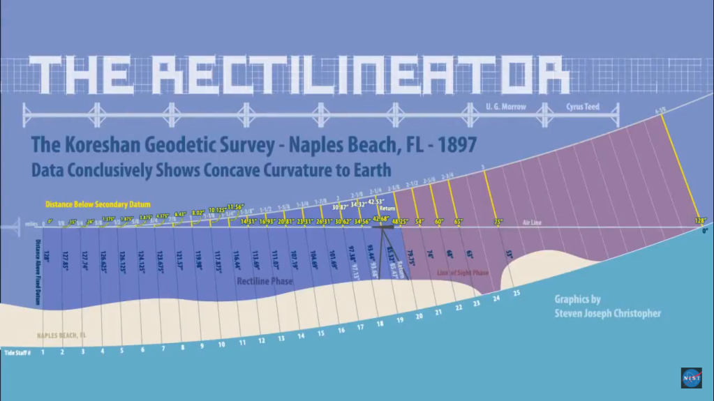
They kept repeating this process down the four and one eighth mile stretch, adjusting the horizontal beam up or down to keep it level with the last. At every eighth of a mile, the height of the horizontal support was measured against the water level beneath, as the water plane is always level to the Earth. However, the water was of course tidal, the level of which had to be measured. This was done by an apparatus called a caisson which is just an artificially created perforated basin allowing the water to be still so it can be easily measured. This possibly could be a weaker point in the experiment as the height of the tide stick (128 inches) in the caisson had to be level with the height of the tide stick on the shore where the original supports had begun very close by. This was done by line of sight with a telescope. Once the tide stick on the shore was marked with the same level of the tide in the caisson, the shore tide stick was brought to one of the 25 tide stick stations along the line (eighth of a mile) where the waterline was currently being measured.
If the distance between the waterline and the horizontal support was the same at each eighth of a mile, then this would prove that the Earth was flat. If the distance continually grew, it was convex (the earth dipping down); and if the distance decreased, it was concave (the Earth curving upwards). Simanek has even added his own calculations at the end.
Calculated Date Dist. Height Height ratio of Radius Dev. 1897 (miles) above below curvature (miles) % datum 2nd (inches) (inches) datum (in) Mar 18 0.000 128.000 0.000 19 0.125 127.850 0.150 0.020 3300.0 -18.5 23 0.250 127.740 0.260 -0.352 7615.4 88.0 24 0.375 126.625 1.375 0.568 3240.0 -20.0 25 0.500 126.125 1.875 0.625 4224.0 4.3 27 0.625 124.125 3.875 2.650 3193.5 -21.2 30 0.750 123.675 4.325 3.048 4120.2 1.7 31 0.875 121.570 6.430 4.583 3772.2 -6.9 Apr 1 1.000 119.980 8.020 6.172 3950.1 -2.5 2 1.125 117.875 10.125 8.355 3960.0 -2.2 8 1.250 116.440 11.560 9.468 4282.0 5.7 9 1.375 113.690 14.310 11.625 4185.5 3.3 13 1.500 111.070 16.930 13.680 4210.3 3.9 14 1.625 107.190 20.810 17.620 4019.9 -0.8 14 1.750 104.690 23.310 20.560 4162.2 2.8 15 1.875 101.690 26.310 22.655 4233.2 4.5 16 2.000 97.380 30.620 26.495 4138.5 2.2 24 2.125 93.440 34.560 28.530 4139.3 2.2 26 2.250 85.320 42.680 35.835 3757.7 -7.2 27 2.375 79.750 48.250 42.590 3703.5 -8.6 May 8 2.500 74.000 54.000 48.125 3666.7 -9.5 8 2.625 68.000 60.000 54.500 3638.3 -10.2 8 2.750 63.000 65.000 95.000 3685.8 -9.0 . 8 3.000 53.000 75.000 3801.6 -6.1 … 8 4.125 0 128.000 4211.4 4.0 Average of the signed deviations: -3x10-14 % Earth’s radius, averaged from 1/8 mile curvatures: 4050.5 mile Average deviation of data values from the mean: 10.2 % Average deviation of the mean: 2.1 % Modern value of Earth’s radius: 3963.5 Discrepancy: 2.2 %
Ulysses G. Morrow’s Naples Survey Data. (The first four columns are from The Cellular Cosmogony (1898). The last three columns, and the summary results below, have been added, newly computed from the Morrow data.)
These decreasing distances conclusively show the Earth to be concave. Even Donald Simanek concurs that the results look genuine:
Even more remarkable is the fact that the results were consistent with an Earth circumference of 25,000 miles. Looking at the data with more modern techniques of data analysis than the Morrow team used, the data show that value to have an experimental uncertainty of a bit over 2%. It differs from the modern value by only about 2% also.
The fact that the average of the signed deviations is so small indicates that the individual values fluctuate about equally above and below the mean. This is an indication that the data is reasonably normal, and the distribution of random errors isn’t skewed. While the individual values fluctuate about 10% from the mean, the average deviation of the mean is only about 2%, benefiting from the process of averaging 24 values. This “average deviation” measure is comparable, as a measure of “goodness of the result, to the standard deviation of the mean, a measure more commonly seen in research papers today.
So far, looking only at the data, this would seem to be a good experiment, with measurement uncertainties consistent with the instruments and methods used.
However, it wasn’t just the distance to the waterline that was being measured, but also the angle of two plumb lines on each of the cross-arms, the location of the bubble in a spirit level, the divergence of the air line and horizontal on the mercurial geodetic level, and the space between the front straight edge and the horizon. Basically, the same apparatus were used which made sure the first support was level at the beginning of the experiment.
If the earth were convex, the line would extend into space, as before explained; as the line would proceed, the bubble in the spirit level would shift at each successive application, more and more toward the south from the central division of the scale, while the plumbline hanging in the direction of the perpendicular, or the earth’s radii at the various stations, would hang toward the initial station. If concave, the conditions and positions of the levels and plumb would be the reverse of those on a convex surface; if flat, they would be the same continually, as at the beginning of the line…
(and looking down the horizon)
…On a convex arc, the straight-edges and the horizon line would appear to converge toward the north with increasing angle, as the line proceeded; if flat, their original parallel relations would be apparent throughout the line; and if concave, the apparent convergence would be toward the south, or in the direction of the movement of the apparatus.
Although the level of the supports was tested every eighth of a mile, the equipment wasn’t sensitive enough to give accurate readings for the first few tests and so the readings given were at 1 mile, 2 miles, and 2 and three eighth miles. Here all the results were also agreeing with a concave Earth very nearly 25,000 miles in circumference.
The bubble had shifted a little – toward the north, or rear section of the apparatus. From the first point of the manifest deviation until the end of the line, the angle increased proportionately to the distance traversed. This was corroborated also by the position of the plumb line, and the observed increase of angle between the straight-edges and horizon, always converging toward the south.
Results
Spirit Level, shift of bubble toward north end of the vial, as measured on the graduated scale:
1 mi., .0375 in.; 2 miles, .077 in.; 2⅜ mi., .089 in.
Plumbline, measurement on arc of 4 feet radius, as related to right-angled cross-arms: .
1 mi., .015 in.; 2 mi., .037 in.; 2⅜ mi., .044 in.
Mercurial geodetic level, indicating angle of divergence of air line and horizontal at points of test, for the space of 12 feet:
1 mi., .042 in.; 2 mi., .094 in.; 2⅜ mi., .115 in.
The Horizon, indicating angle for space of 36 feet, as accurately as could be measured with the eye at a distance of 15 feet from the apparatus:
1 mi., .15 in.; 2 mi., .34 in.; 2⅜ mi., .51 in.
You may think, well, the supports were on sand under water; could they subside and give skewered results? The results were very consistent however, not showing any irregularities such as one moment showing a convex earth and the next a concave one. They even addressed this possible issue by meticulously retracing the same line backwards three eighths of a mile one time and got the same results. Another retraction of 228 feet is also described in more detail on page 103/4 which gave exactly the same result as the original line to within 0.0001 inch!
It is supposed that settling played an important part in the descent of the line surveyed; if so, why should the line descend .15 of an inch for the first eighth of a mile, and 6 inches for the eighth between the 19th and 20th tide stakes? If settling produced the descent, this would be manifest by returning over the same line. We returned over the same line for a distance of ⅜ of a mile, to ascertain if there would be any deviation. The fact that the horizontal axis of the apparatus projected the line on the return survey to the same points on the record stakes indicating the air line in the forward survey, is proof of the fact that the factors of settling, if any existed, were absolutely neutralized, for they did not swerve the apparatus from a true and directed rectiline course. Let those who make such objections explain how the exact and definite ratio was obtained, if we did not extend a rectiline from the beginning of the survey.
(page 103/4) …228 feet were measured; a stake was fixed at the beginning, with brass plate bearing fine line coincidental with the horizontal hair-line of the apparatus. 19 forward adjustments were made, and the direction retraced; at the last return adjustment, the section was found to be in the exact same place as originally, with the hair-line precisely over the fine line on the brass plate. The results were obtained by observations with the microscope; the apparatus returned to the same point, after traversing the space of 456 feet, without deviation of 0.0001 of an inch.
One other possible problem may be the material. Despite the supports being 12-year seasoned mahogany, did the wood or brass expand or contract with the slight changes of temperature from one day to the next or through the possible absorption of seawater? The supports were however manufactured meticulously, as we have already seen, so this is highly doubtful. Also, the results would again not be so consistent as they were. The authors reply to this potential issue with:
A source of inaccuracy is also attributed to the contraction and expansion of the material of which the apparatus is constructed. Those who make this objection have never seen the apparatus, and consequently cannot appreciate the fact that the plan of its construction obviates the effect of whatever contraction or expansion occurred.
In fact, this experiment was not only precisely planned and implemented with each action repeatedly and independently checked, logged and signed off by everyone involved, but these independent external observers were adherers to the Copernican system!
Every item of adjustment, test, observation, and measurement was checked in the check record book, and described in detail in the daily record book, to which are appended the signatures of all operators and witnesses. The facts of preparation, measurements, and survey contained in this work are taken from the records, attested and sworn to by the entire Geodetic Staff and the investigating committee.
(page 104)… This test (the retracing of the three eighths of a mile) was in accordance with the plans of the critics on the field of observations, representing the Copernican system, who were doing all in their power to prove the instrument inaccurate.
It was also very thorough and painstaking work.
(Page 101) – The Geodetic staff of the Koreshan Unity reached the Operating Station January 2, 1897, with apparatus and all appurtenances and instruments, and plans of operations, which required five months’ careful observations and accurate work to execute.
Because this experiment was so iron-clad, the skeptic Simanek’s only retort is that somehow the supports must have all curved downwards due to experimental error or poor construction, despite all the evidence already mentioned proving otherwise and despite the fact that they inverted the horizontal supports with every addition!
If you think that is desperate, Skeptoid magazine claim the beams must have sagged continually downwards due to them being only supported at one end, with the results coincidentally exactly coinciding with a concave Earth! As the reader now knows, the supports weren’t supported at any end of course, but underneath on each post (standard) by brass castings. The ends were bolted to prevent any possible further movement from occurring and did not carry any weight of either support.
Conclusion
The only fault with this experiment is that it is over 100 years old and has never been publicly repeated since (for obvious reasons), which doesn’t make it 100% conclusive, but very close. Does the Rectilineator show a concave Earth? Extremely likely – 99%. Luckily, Steven Christopher and his team are reproducing this experiment on South Padre island Texas as of October 2015. If they reproduce the same results, then we can increase this percentage to 100%.
Via https://web.archive.org/web/20201112011708/http://www.wildheretic.com/concave-earth-theory/6/
")